Marine Tail Shaft and Intermediate Shaft Machining
| Product name: | Marine Tail Shaft and Intermediate Shaft Machining |
| Keywords: | Marine Tail Shaft, Marine Intermediate Shaft |
| Industry: | Transportation - Ship industry |
| Process: | Machining - Five-axis machining |
| Material: | Stainless steel |
Processing manufacturer
- There are 52 manufacturers that provide similar products
- There are 138 manufacturers that provide this processing technology
- There are 98 manufacturers that provide this material processing service
- There are 190 manufacturers that provide this industry processing service
Product details
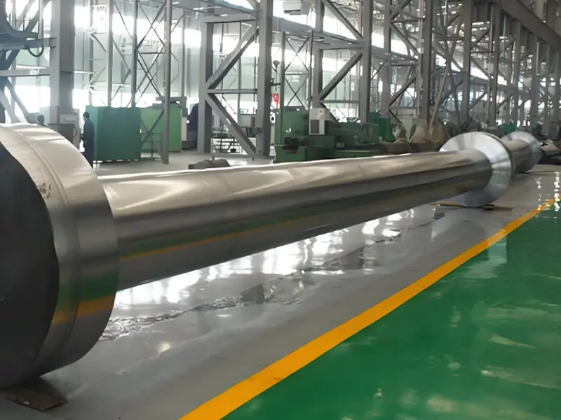
Marine tail shafts and intermediate shafts are critical components in a ships propulsion system, used to transmit power from the main engine to the propeller, propelling the ship forward.
1. Marine Tail Shaft
The tail shaft is the shaft in a ships propulsion system that is directly connected to the propeller, located at the stern, and is responsible for transmitting power from the intermediate shaft or main engine to the propeller, driving the ship forward.
Function
- Power Transmission: Transmits the rotational power from the intermediate shaft or reduction gearbox to the propeller.
- Load Bearing: Withstands the thrust and torque of the propeller, as well as vibrations and shocks during ship navigation.
- Sealing and Lubrication: Prevents seawater from entering the hull through the tail shaft sealing device (such as oil seals or water seals), while reducing friction through the lubrication system.
Design and Structural Features
- Structure:
- Typically a long cylindrical shaft, with a length depending on the ships size (from a few meters to tens of meters).
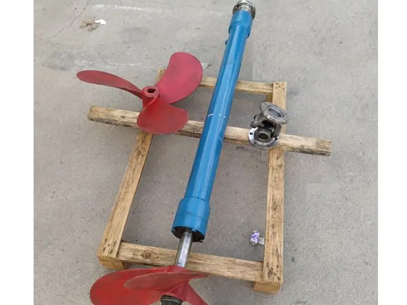
- One end is connected to the propeller, and the other end is connected to the intermediate shaft or gearbox via a coupling.
- Often equipped with a Stern Tube, which contains bearings (usually oil-lubricated or water-lubricated bearings) to support the rotation of the shaft.
- Tail Shaft Seal:
- Oil-lubricated seal: Uses oil seals and stuffing boxes to prevent seawater from seeping in.
- Water-lubricated seal: Employs wear-resistant materials (such as rubber or composite materials), suitable for environmental protection requirements.
- Bearing: The stern tube usually has front and rear tail shaft bearings, made of white metal, copper alloy, or polymer composite materials.
- Size: The diameter is designed according to the main engine power and propeller load, with a common range of 50mm~500mm.
Material
- Forged Steel (e.g., 35CrMo, 40CrNiMo): High strength (tensile strength ≥ 600 MPa), high toughness, suitable for large ships.
- Stainless Steel (e.g., 316L, 17-4PH): Corrosion-resistant, suitable for long-term exposure to seawater.
- Surface Treatment: The exposed parts of the tail shaft are often chrome-plated or coated with an anti-corrosion layer, and the shaft sleeve may use copper alloy or stainless steel for corrosion protection.
Application Scenarios
- Commercial ships (such as bulk carriers, tankers, container ships).
- Warships, fishing boats, yachts, etc.
- Special ships (such as submarines, research vessels), requiring higher precision tail shaft design.
2. Marine Intermediate Shaft
The intermediate shaft is the transmission shaft connecting the main engine (or reduction gearbox) and the tail shaft, located in the ships engine room, and is responsible for transmitting the main engine power to the tail shaft.
Function
- Power Transmission: Transmits the rotational force of the main engine or gearbox to the tail shaft, driving the propeller.
- Vibration Damping and Alignment: Absorbs vibrations through couplings and intermediate bearings to ensure smooth power transmission.
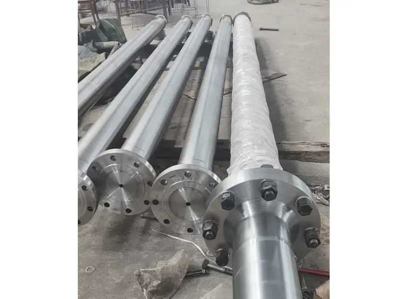
- Length Adjustment: According to the engine room layout, the intermediate shaft can be composed of multiple sections, connected by flanges or couplings.
Design and Structural Features
- Structure:
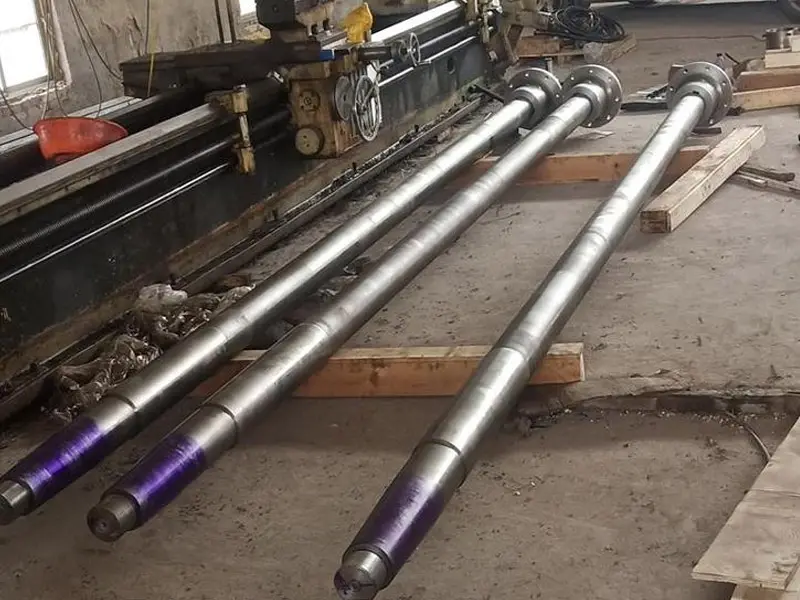
- Consists of single or multiple cylindrical shafts, with a length depending on the distance from the engine room to the tail shaft (from a few meters to tens of meters).
- Connected to the main engine, gearbox, and tail shaft through flanges, couplings, or keyways.
- Equipped with intermediate bearings (usually plain bearings or roller bearings) to support the rotation of the shaft.
- Alignment Requirements: The intermediate shaft needs to be precisely aligned (deviation < 0.05mm/m) to avoid vibration and premature bearing wear.
- Coupling: Elastic couplings (such as rubber or steel spring type) are commonly used to absorb main engine vibrations and protect the shafting.
- Size: The diameter depends on the main engine power (tens of millimeters to hundreds of millimeters), generally slightly smaller than the tail shaft.
Material
- Forged Steel (e.g., 40Cr, 42CrMo): High strength, high toughness, suitable for high-power ships.
- Alloy Steel (e.g., 35CrNiMo): Used in high-load scenarios, with excellent fatigue resistance.
- Surface Treatment: The shaft surface is polished or chrome-plated to reduce friction; the bearing housing may use copper alloy or white metal.
Application Scenarios
- Large ships: Intermediate shafts are essential when the distance between the main engine and the tail shaft is long (such as bulk carriers, tankers).
- Medium and small ships: If the main engine is close to the tail shaft, the intermediate shaft may be omitted and directly connected to the tail shaft.
- Multi-shaft ships: Such as twin-screw ships, each propulsion system requires an independent intermediate shaft.
3. Relationship between Tail Shaft and Intermediate Shaft
- Power Transmission Chain: Main engine → Intermediate shaft (if any) → Tail shaft → Propeller, forming a complete propulsion system.
- Design Collaboration:
- The diameter, material, and bearings of both need to be designed uniformly to ensure power transmission efficiency and system stability.
- The tail shaft is directly exposed to seawater and requires stronger anti-corrosion measures; the intermediate shaft is in the engine room, focusing on alignment and vibration damping.
- Installation and Calibration: A laser alignment instrument or dial indicator is required during installation to ensure shafting deviation < 0.05mm/m to prevent vibration and wear.
Previous article : Marine Anchor Chain Wheel
Similar products
More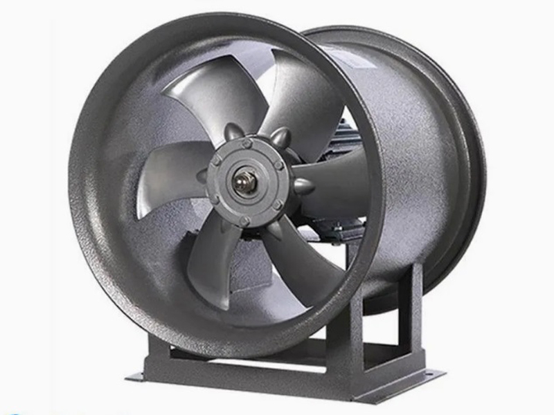
What are the machining processes used for processing axial fan housings
- Process : Sheet metal - Welding
- Material : Carbon steel
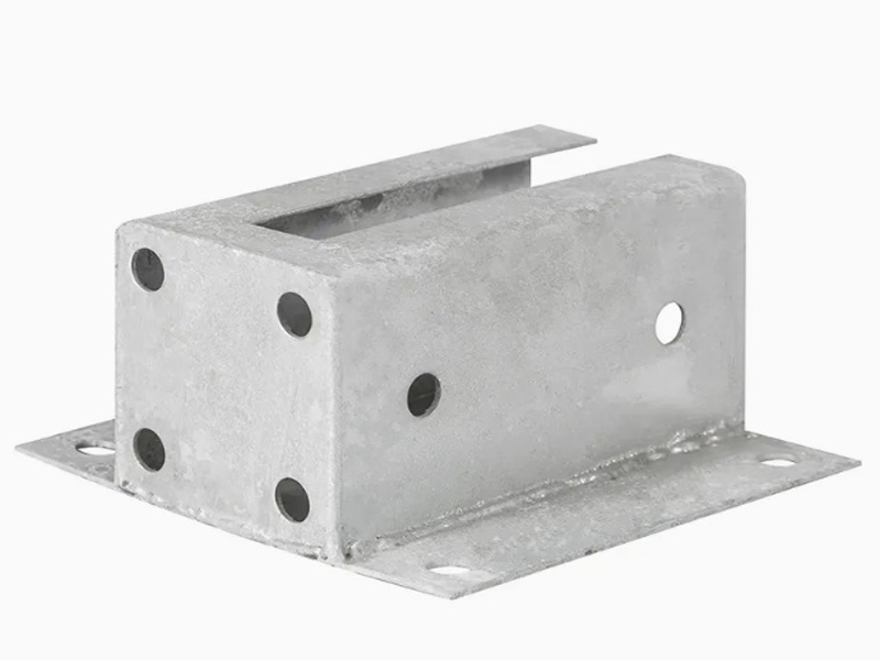
Machining Process Analysis of Carbon Steel Fixed Anchor Plates
- Process : Machining - CNC milling or milling machining
- Material : Carbon steel
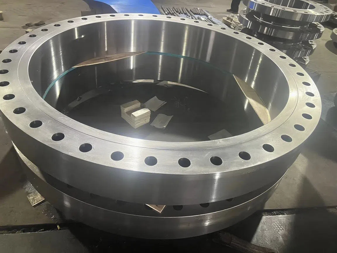
Heavy-Walled Flange Milling-Turning Machining and Flaw Detection
- Process : Machining - Turning Milling compound
- Material : Alloy steel
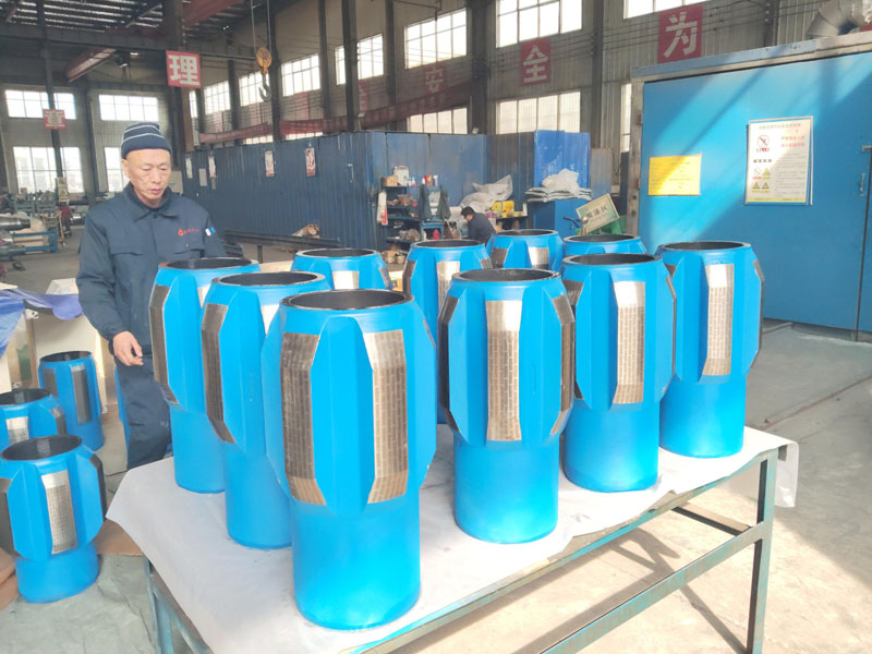
Drill Stabilizers Applied in Oil Drilling Platforms
- Process : Machining - Five-axis machining
- Material : Alloy steel
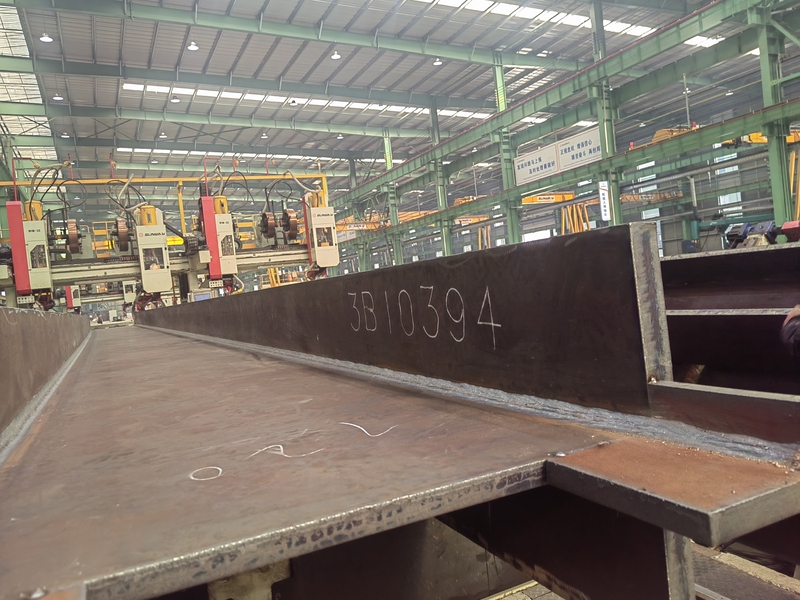
Custom Fabrication of S355JR Welded H-Beams for Construction Projects
- Process : Sheet metal - Welding
- Material : Carbon steel
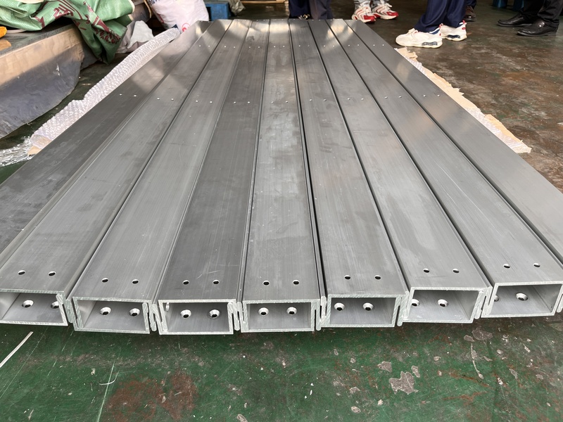
Precision Machining of U-Steel Profiles for Building Applications
- Process : Stamping - General stamping
- Material : Aluminum
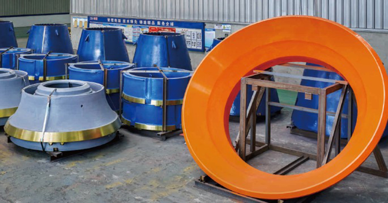
Cone Crusher Mantle
- Process : -
- Material :
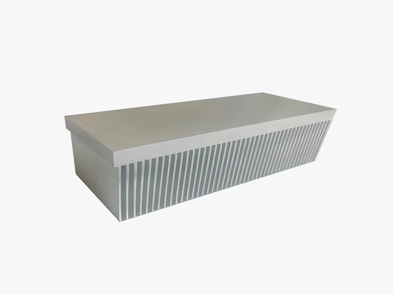
Innovative skiving technology: Breaking through the bottleneck of high-density heat dissipation technology
- Process : Surface treatment - Others
- Material : Alloy steel
More products
MoreWhat are the machining processes used for processing axial fan housings
- Process : Sheet metal - Welding
- Material : Carbon steel
Machining Process Analysis of Carbon Steel Fixed Anchor Plates
- Process : Machining - CNC milling or milling machining
- Material : Carbon steel
Heavy-Walled Flange Milling-Turning Machining and Flaw Detection
- Process : Machining - Turning Milling compound
- Material : Alloy steel
Drill Stabilizers Applied in Oil Drilling Platforms
- Process : Machining - Five-axis machining
- Material : Alloy steel
Custom Fabrication of S355JR Welded H-Beams for Construction Projects
- Process : Sheet metal - Welding
- Material : Carbon steel
Precision Machining of U-Steel Profiles for Building Applications
- Process : Stamping - General stamping
- Material : Aluminum
Cone Crusher Mantle
- Process : -
- Material :
Innovative skiving technology: Breaking through the bottleneck of high-density heat dissipation technology
- Process : Surface treatment - Others
- Material : Alloy steel