Railway Wheel Chock Processing
| Product name: | Railway Wheel Chock Processing |
| Keywords: | Railway Wheel Chock, Track Chock |
| Industry: | Transportation - Rail transportation |
| Process: | Casting - Precision casting |
| Material: | Carbon steel |
Processing manufacturer
- There are 42 manufacturers that provide similar products
- There are 128 manufacturers that provide this processing technology
- There are 84 manufacturers that provide this material processing service
- There are 157 manufacturers that provide this industry processing service
Product details
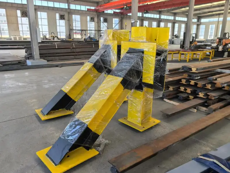
A railway wheel chock is a fixed or movable metal device installed on rails to restrict the movement of trains or vehicles by contacting the wheels or axles. It is typically designed as a wedge-shaped or hook-shaped structure that acts directly on the wheels, preventing them from sliding along the track, especially on slopes, in marshalling yards, or in parking areas. Chocks are an important part of the railway safety system and comply with relevant standards (such as Chinas "Railway Technical Management Regulations" or international UIC standards).
Functions
- Prevent Sliding: Prevents trains from sliding due to gravity or external forces (such as wind) on slopes or in parking areas.
- Safety Protection: Prevents trains or vehicles from accidentally moving, leading to derailment, collisions, or personal injury.
- Temporary Parking: Secures vehicle positions in marshalling yards or maintenance points to facilitate operations or repairs.
- Emergency Braking Assistance: Serves as an additional braking measure in emergencies to prevent further train movement.
- Maintenance Operations: Ensures train stability during vehicle maintenance or cargo loading and unloading.
Types
Railway wheel chocks can be divided into the following types according to their structure, use, and installation method:
(1) Fixed Wheel Chocks
- Features:
- Directly fixed to the track, usually connected to the sleepers or track by bolts or welding.
- The structure is a steel wedge or hook shape that contacts the outer edge of the wheel to prevent sliding.
- Approximately 100-150mm in height, with a width adapted to track standards (such as 1435mm standard gauge).
- Applicable Scenarios: Railway terminals, freight yards, or long-term parking points.
- Advantages: Simple structure, high stability, and low maintenance costs.
- Disadvantages: Immovable, poor flexibility, and requires fixed installation.
(2) Movable Wheel Chocks
- Features:
- Removable or sliding design, manually placed on the track, weighing approximately 5-20kg, and can be operated by one person.
- Often wedge-shaped or U-shaped, equipped with locking devices (such as springs or bolts) to fix it on the track.
- The surface has an anti-slip design to adapt to different track types (such as 50kg/m, 60kg/m rails).
- Applicable Scenarios: Temporary parking, maintenance operations, marshalling yards.
- Advantages: High flexibility, quick deployment and removal, suitable for temporary use.
- Disadvantages: Slightly weaker than fixed type, requires regular inspection of fixing devices.
(3) Hydraulic/Mechanical Wheel Chocks
- Features:
- Uses hydraulic or mechanical lifting devices, usually hidden below the track, and raised when needed to block the wheels.
- Adjustable height (100-200mm), equipped with a control system (manual or electric).
- Steel structure, weighing 50-200kg, requires a dedicated foundation for fixation.
- Applicable Scenarios: Engine terminals and EMU parking lots with high safety requirements.
- Advantages: High degree of automation, can be remotely controlled, and does not affect track passage when lowered.
- Disadvantages: High cost, complex maintenance, and requires power support.
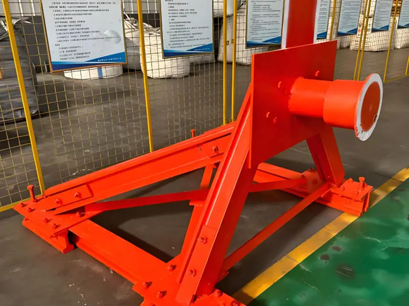
(4) Buffer Wheel Chocks
- Features:
- Equipped with buffer devices (such as springs, hydraulic dampers) to absorb low-speed train impact energy (approximately 50-200 kJ).
- Usually fixed, installed at the end of the track, equipped with steel or rubber buffer heads.
- Designed to comply with EN 15227 or UIC 528 standards, with an impact resistance of up to 500 kN.
- Applicable Scenarios: Railway terminals, the end of marshalling yards, to prevent derailment.
- Advantages: Protects trains and tracks, and reduces impact damage.
- Disadvantages: Complex structure, high installation and maintenance costs.
(5) Simple Wheel Chocks
- Features:
- Small steel or cast iron wedge-shaped device, weighing 3-10kg, placed directly on the track and fixed by friction.
- Commonly used in low-speed scenarios (such as <10km/h), no fixed installation required.
- Applicable Scenarios: Temporary parking, light vehicles, or low-risk areas.
- Advantages: Low cost, high portability, and simple operation.
- Disadvantages: Limited resistance, easy to move, not suitable for heavy trains.
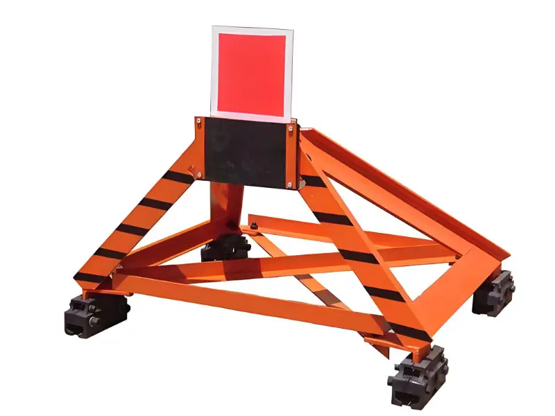
Materials and Structural Features
- Materials:
- Carbon Steel: Q235 (yield strength 235 MPa) or Q345 (yield strength 345 MPa), thickness 10-20mm, low cost, suitable for mass production.
- Cast Iron: Ductile iron (such as QT500-7), strong impact resistance, suitable for simple or fixed wheel chocks.
- Stainless Steel: 304/316, corrosion-resistant, suitable for coastal or high-humidity environments.
- Buffer Material: Rubber or polyurethane, used in buffer wheel chocks to absorb impact energy.
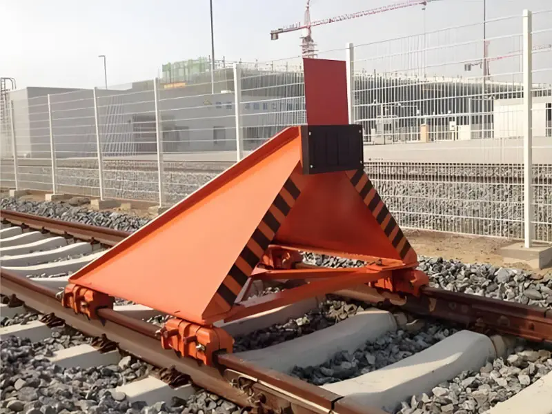
- Structural Design:
- Shape: Wedge-shaped, U-shaped, or hook-shaped, the contact surface is adapted to the wheel profile (wheel diameter 800-1000mm).
- Resistance: Design resistance of 100-500 kN, meeting different train weights (freight car 50-100 tons, passenger car 20-50 tons).
- Fixing Method: Bolts (grade 8.8 or higher), welding, or clamping devices, adapted to standard gauge (1435mm).
- Surface Treatment: Hot-dip galvanizing (thickness 60-80μm) or spraying (80-120μm), to prevent rust and last for 10-15 years.
- Visibility: Surface coated with orange/white reflective paint, compliant with GB 5768 or MUTCD standards.
Previous article : Interpretation of Anti-Settlement Design Code for Crude Oil Tank Foundations in Coastal Areas
Next article : Subway Traction System Motor End Cover
Similar products
More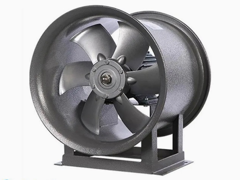
What are the machining processes used for processing axial fan housings
- Process : Sheet metal - Welding
- Material : Carbon steel
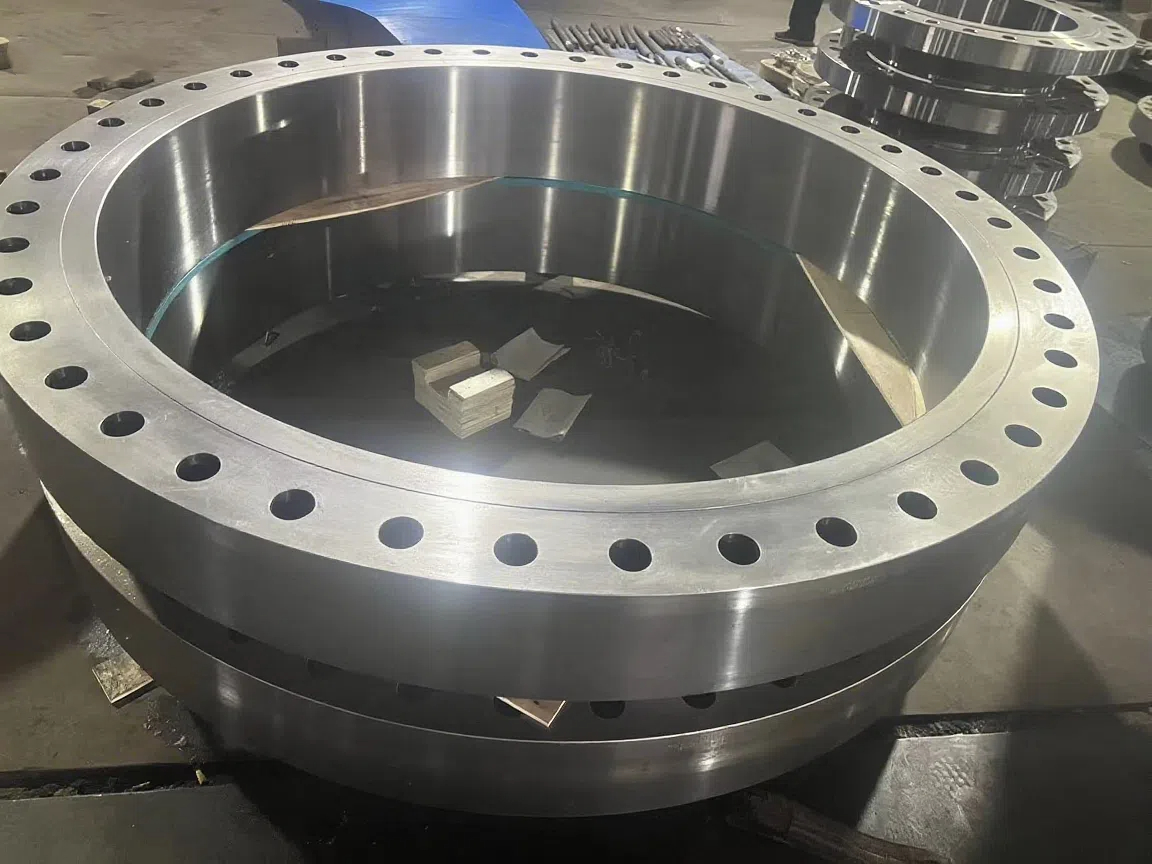
Heavy-Walled Flange Milling-Turning Machining and Flaw Detection
- Process : Machining - Turning Milling compound
- Material : Alloy steel
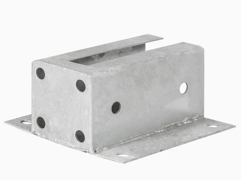
Machining Process Analysis of Carbon Steel Fixed Anchor Plates
- Process : Machining - CNC milling or milling machining
- Material : Carbon steel
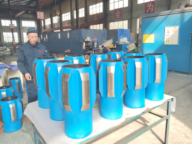
Drill Stabilizers Applied in Oil Drilling Platforms
- Process : Machining - Five-axis machining
- Material : Alloy steel
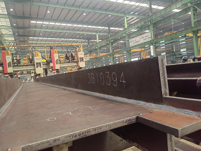
Custom Fabrication of S355JR Welded H-Beams for Construction Projects
- Process : Sheet metal - Welding
- Material : Carbon steel
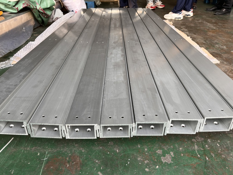
Precision Machining of U-Steel Profiles for Building Applications
- Process : Stamping - General stamping
- Material : Aluminum
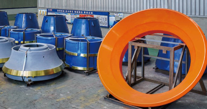
Cone Crusher Mantle
- Process : -
- Material :
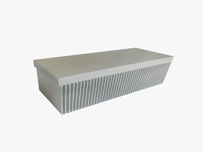
Innovative skiving technology: Breaking through the bottleneck of high-density heat dissipation technology
- Process : Surface treatment - Others
- Material : Alloy steel
More products
MoreWhat are the machining processes used for processing axial fan housings
- Process : Sheet metal - Welding
- Material : Carbon steel
Heavy-Walled Flange Milling-Turning Machining and Flaw Detection
- Process : Machining - Turning Milling compound
- Material : Alloy steel
Machining Process Analysis of Carbon Steel Fixed Anchor Plates
- Process : Machining - CNC milling or milling machining
- Material : Carbon steel
Drill Stabilizers Applied in Oil Drilling Platforms
- Process : Machining - Five-axis machining
- Material : Alloy steel
Custom Fabrication of S355JR Welded H-Beams for Construction Projects
- Process : Sheet metal - Welding
- Material : Carbon steel
Precision Machining of U-Steel Profiles for Building Applications
- Process : Stamping - General stamping
- Material : Aluminum
Cone Crusher Mantle
- Process : -
- Material :
Innovative skiving technology: Breaking through the bottleneck of high-density heat dissipation technology
- Process : Surface treatment - Others
- Material : Alloy steel