How to Process Movable Steel Vehicle Barriers
| Product name: | How to Process Movable Steel Vehicle Barriers |
| Keywords: | Movable Steel Vehicle Barriers |
| Industry: | Transportation - Transportation products industry |
| Process: | Sheet metal - Welding |
| Material: | Carbon steel |
Processing manufacturer
- There are 37 manufacturers that provide similar products
- There are 197 manufacturers that provide this processing technology
- There are 73 manufacturers that provide this material processing service
- There are 100 manufacturers that provide this industry processing service
Product details
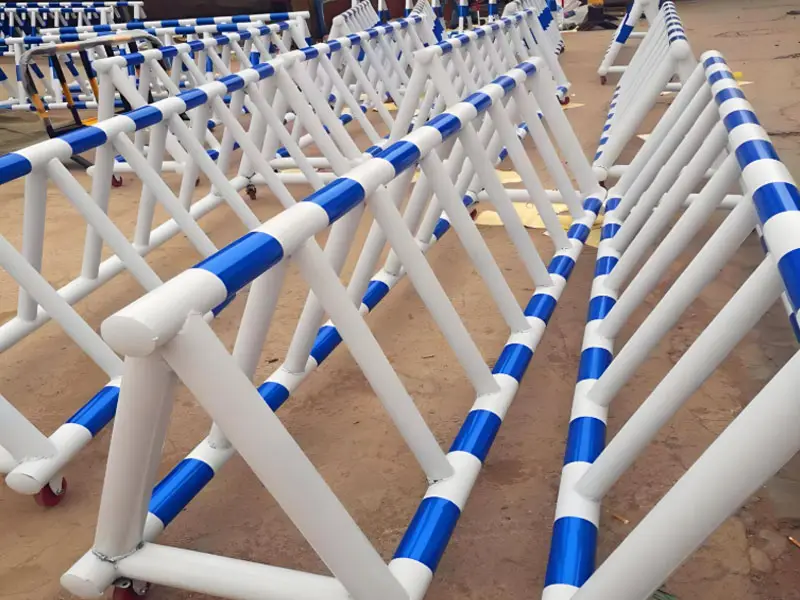
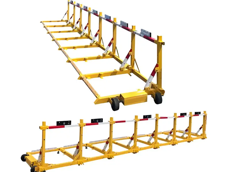
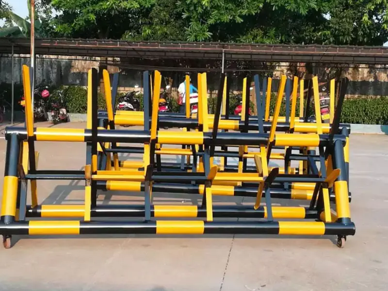
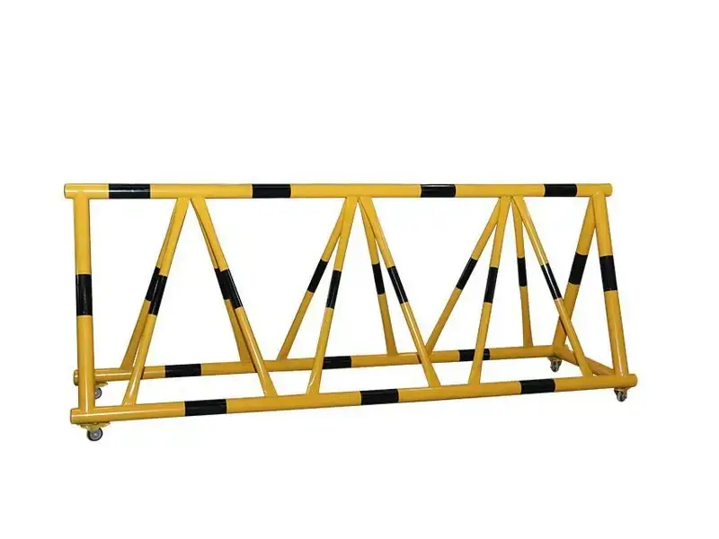
The processing of movable steel vehicle barriers is a precise manufacturing process aimed at producing high-strength, portable, and durable traffic safety facilities for temporarily blocking vehicle passage.
1. Material Selection
- Main Materials:
- Carbon Steel: Q235 (yield strength 235 MPa) or Q345 (yield strength 345 MPa), thickness 3-10mm, suitable for high-strength requirements, and low cost.
- Stainless Steel: 304/316, corrosion-resistant, suitable for coastal or high-humidity environments, no additional coating required.
- Material Properties:
- Density: Approximately 7850 kg/m³ (carbon steel), 7800 kg/m³ (stainless steel).
- Youngs Modulus: 2E11 Pa, requires good toughness and impact resistance.
- Surface Treatment Requirements: Carbon steel requires hot-dip galvanizing (thickness 60-80μm) or spraying (80-120μm) for corrosion protection, stainless steel can be directly wire-drawn.
- Material Selection Requirements:
- Use new hot-rolled steel plates, avoid secondary materials (scrap steel is prone to deformation or insufficient strength).
- Inspect the steel surface to ensure it is free of cracks, slag inclusions, or severe rust.
2. Processing Technology Flow
The processing of movable steel vehicle barriers involves design, material preparation, component forming, welding, surface treatment, assembly, and testing. The following are detailed steps:
(1)Design and Preparation
- Design:
- Use CAD or SolidWorks for 3D modeling, designing L-shaped, U-shaped, wedge-shaped, or bollard structures.
- Consider impact resistance (energy absorption 500-1000 kJ, compliant with ASTM F2656 M30/M40 or PAS68 standards).
- Optimize portability, control the weight of a single unit to 20-60kg, and use modular design for easy connection and handling.
- Finite element analysis (FEA) verifies structural strength, simulating wind loads (1.0-1.5 kN/m²) and vehicle impacts (4.5-15 tons, 30-50km/h).
- Material Preparation:
- Purchase fixed-size steel plates or pipes (Q235/Q345 or stainless steel), and cut them to the required dimensions (accuracy ±1mm).
- Inspect the surface quality of the steel, and remove oil stains and rust (acid pickling or steam cleaning can be used).
(2)Component Forming
- Stamping Forming:
- Equipment: Hydraulic press (500-1000 tons), equipped with special molds (insert type, suitable for multiple varieties).
- Process: Stamp the steel plate into L-shaped, U-shaped, or wedge-shaped components, control the springback rate <2%, tolerance ±0.5mm.
- Note: Molds need to be maintained regularly to reduce wear and ensure forming accuracy.
- Roll Forming:
- Equipment: CNC roll forming machine.
- Process: Steel plates or coils are gradually formed into pipes or profiles through multiple roll forming dies, suitable for straight components, accuracy ±0.5mm.
- Follow-up: Plasma or laser cutting to trim the edges, flatness <±1mm.
- Pipe Bending:
- Equipment: CNC pipe bending machine.
- Process: Bend the steel into arcs or specific angles (such as the top arc of a bollard), angle accuracy ±0.5°.
- Note: Control the bending speed to avoid stress concentration, and preheat the steel (200-300°C) if necessary to improve ductility.
(3)Hole Processing
- Hole Position Design:
- Process connection holes (for modular connection, pins or chains) or mounting holes (for ground anchors or wheels), hole diameter 10-50mm, quantity 50-200 pieces/unit.
- Hole positions need to be evenly distributed to release processing stress, tolerance ±0.2mm.
- Processing Method:
- CNC Punching: Using CNC punch press, high efficiency (20-30 holes/minute), suitable for multi-variety, small-batch production.
- Mold Punching: Special punching die, suitable for mass production, high precision but high mold adjustment cost.
- Plasma Cutting: Used for large-size holes or complex shapes, accuracy ±1mm.
- Drill Press Drilling: Used for temporary adjustments or small-batch production, low efficiency.
- Note: Hole edges need to be deburred, verticality deviation <0.5°, to avoid affecting assembly or strength.
(4)Welding
- Welding Method:
- TIG Welding (Gas Tungsten Arc Welding): Suitable for stainless steel or thin-walled steel (<5mm), fine weld seam, small heat-affected zone.
- MIG Welding (Gas Metal Arc Welding): Suitable for carbon steel, high efficiency, suitable for thick plates (5-10mm).
- Weld strength needs to reach more than 90% of the base material, without porosity or cracks.
- Fixture Usage: Use special fixtures for positioning, control welding deformation, dimensional deviation <±1mm.
- Inspection: Ultrasonic or X-ray inspection of weld quality to ensure no internal defects.
- Note: The welding area needs to be pre-cleaned to remove oil stains and oxides to avoid weld defects.
(5)Surface Treatment
- Shot Blasting/Sandblasting:
- Equipment: Shot blasting machine or sandblasting machine, using steel shot (particle size 0.5-1mm) or sand particles.
- Process: Remove oxide layer and rust, surface roughness Ra 3.2-6.3μm, enhance coating adhesion.
- Note: Equipped with dust removal equipment, control noise (<85dB), and meet environmental protection requirements.
- Corrosion Protection:
- Hot-Dip Galvanizing: Immerse in zinc liquid (450-480°C), zinc layer thickness 60-80μm, corrosion resistance 10-15 years.
- Powder Coating: Epoxy primer + polyurethane topcoat (total thickness 80-120μm), colors are mostly orange/white, with reflective effect, compliant with MUTCD or GB 5768 standards.
- Stainless Steel: Wire drawing (roughness Ra 0.8-1.6μm), no additional coating required.
- Reflective Strips: Paste reflective film (3M or similar brand) or mold reflective strips to improve night visibility.
(6)Assembly
- Modular Design: Components are connected by bolts, pins, or chains, some are equipped with wheels (polyurethane or rubber wheels, load-bearing 100-200kg) or handles.
- Trial Assembly: Complete modular assembly in the factory to verify dimensions (deviation <±2mm) and connection stability.
- Accessory Installation: Such as ground anchors (anti-tipping force 10 kN), reflective strips, or LED lights (12-24V low-voltage power supply).
- Note: Bolts need to be high-strength (8.8 grade or above), add anti-loosening washers to ensure long-term use without loosening.
Similar products
More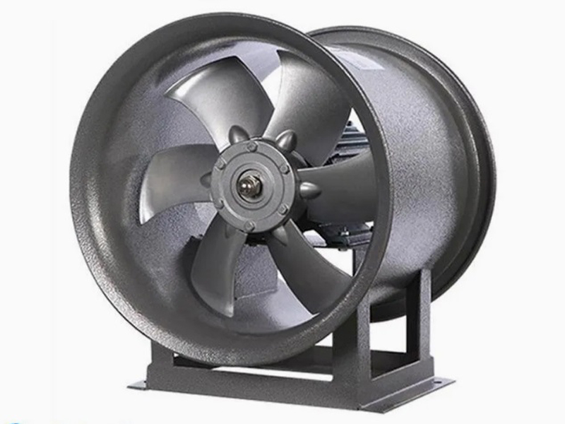
What are the machining processes used for processing axial fan housings
- Process : Sheet metal - Welding
- Material : Carbon steel
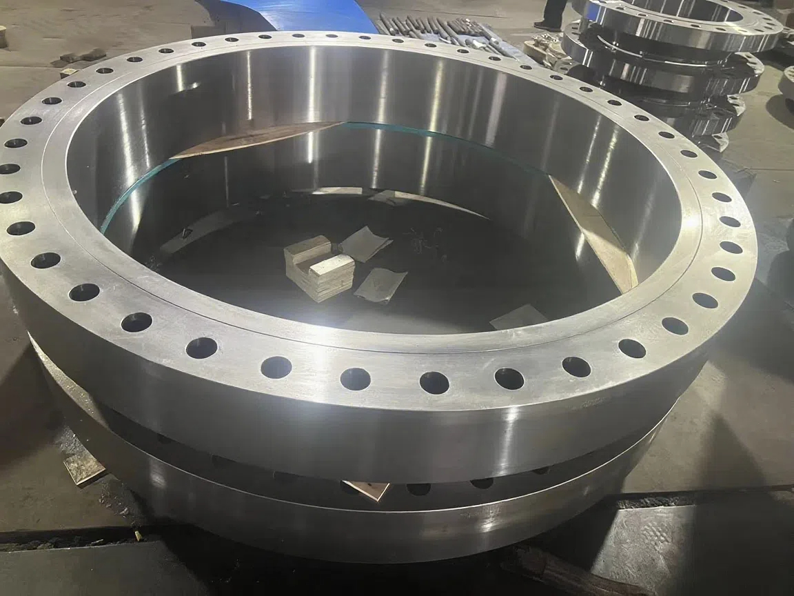
Heavy-Walled Flange Milling-Turning Machining and Flaw Detection
- Process : Machining - Turning Milling compound
- Material : Alloy steel
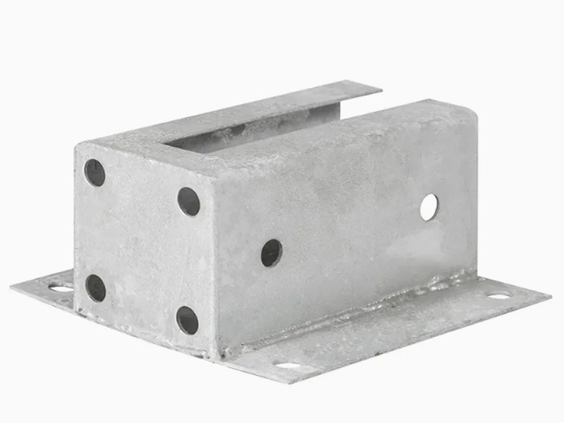
Machining Process Analysis of Carbon Steel Fixed Anchor Plates
- Process : Machining - CNC milling or milling machining
- Material : Carbon steel
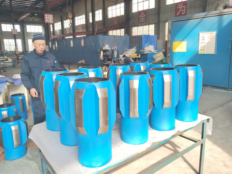
Drill Stabilizers Applied in Oil Drilling Platforms
- Process : Machining - Five-axis machining
- Material : Alloy steel
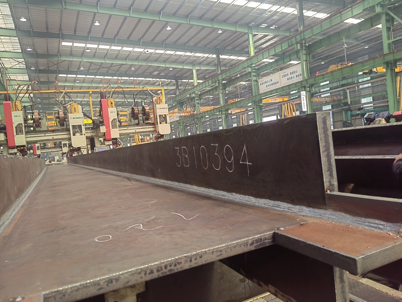
Custom Fabrication of S355JR Welded H-Beams for Construction Projects
- Process : Sheet metal - Welding
- Material : Carbon steel
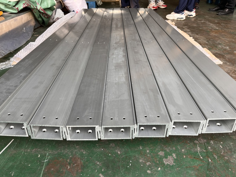
Precision Machining of U-Steel Profiles for Building Applications
- Process : Stamping - General stamping
- Material : Aluminum
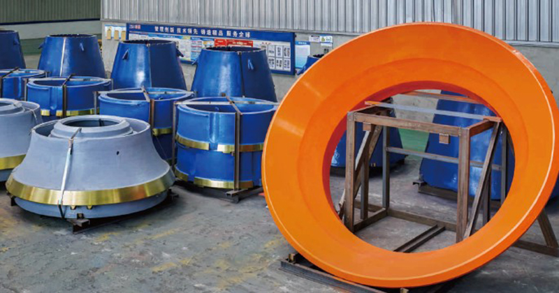
Cone Crusher Mantle
- Process : -
- Material :
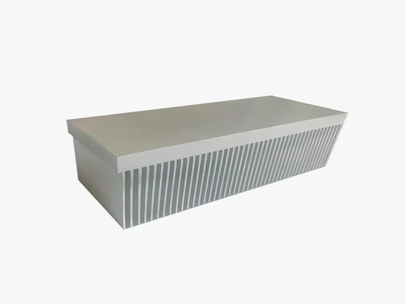
Innovative skiving technology: Breaking through the bottleneck of high-density heat dissipation technology
- Process : Surface treatment - Others
- Material : Alloy steel
More products
MoreWhat are the machining processes used for processing axial fan housings
- Process : Sheet metal - Welding
- Material : Carbon steel
Heavy-Walled Flange Milling-Turning Machining and Flaw Detection
- Process : Machining - Turning Milling compound
- Material : Alloy steel
Machining Process Analysis of Carbon Steel Fixed Anchor Plates
- Process : Machining - CNC milling or milling machining
- Material : Carbon steel
Drill Stabilizers Applied in Oil Drilling Platforms
- Process : Machining - Five-axis machining
- Material : Alloy steel
Custom Fabrication of S355JR Welded H-Beams for Construction Projects
- Process : Sheet metal - Welding
- Material : Carbon steel
Precision Machining of U-Steel Profiles for Building Applications
- Process : Stamping - General stamping
- Material : Aluminum
Cone Crusher Mantle
- Process : -
- Material :
Innovative skiving technology: Breaking through the bottleneck of high-density heat dissipation technology
- Process : Surface treatment - Others
- Material : Alloy steel