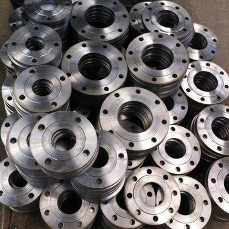
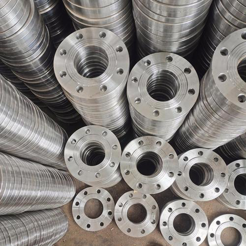
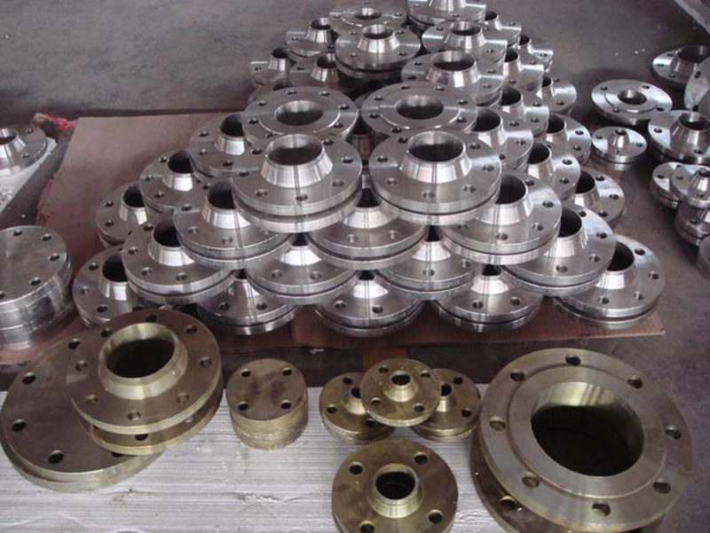
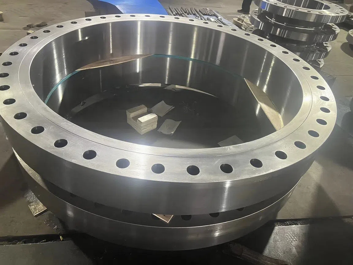
Carbon Steel Flange Installation Guide: Steps and Precautions
| Product name: | Carbon Steel Flange Installation Guide: Steps and Precautions |
| Keywords: | |
| Industry: | Metallurgy and minerals - Exploration industry |
| Process: | - |
| Material: |
Processing manufacturer
- There are 51 manufacturers that provide similar products
- There are 178 manufacturers that provide this processing technology
- There are 89 manufacturers that provide this material processing service
- There are 188 manufacturers that provide this industry processing service
Product details
Material Inspection:
Confirm that the specifications and pressure rating (e.g., Class 150, 300) of the carbon steel flange (common grades such as ASTM A105) meet the design requirements.
Inspect the flange, bolts, nuts, and gaskets for integrity, ensuring no cracks, deformation, or corrosion.
Ensure the gasket type (non-metallic like graphite, metallic like spiral wound gasket) is suitable for the operating conditions.
Tool Preparation:
Torque wrench (for precise control of bolt preload).
Flange alignment tools, cleaning brush, lubricant (such as graphite grease).
Measuring tools (calipers, level).
Pipe Preparation:
Ensure the pipe end face is flat, clean, and free of burrs or dirt.
Check the alignment of the pipe and flange; the deviation should not exceed 1.5mm.
Installation Steps
Cleaning and Inspecting the Flange Face:
Clean the flange sealing surface with a wire brush or solvent to ensure it is free of oil, rust, or foreign objects.
Check the sealing surface roughness (recommended Ra 3.2-6.3μm) to ensure there are no scratches or dents.
Gasket Installation:
Place the gasket between the two flange sealing surfaces, ensuring it is centered and without offset.
Select the gasket thickness according to the operating conditions (usually 1.5-3mm) to avoid affecting the seal due to excessive or insufficient thickness.
Flange Alignment and Temporary Fixation:
Use alignment tools or temporary bolts to ensure the two flanges are parallel, with an axis deviation of <1mm.
Check that the flange gap is uniform; the recommended gap is 2-4mm (depending on the gasket type).
Bolt Installation:
Insert the bolts in a diagonal sequence (star-shaped cross method), applying an appropriate amount of lubricant to reduce friction.
Ensure the bolt specifications (length, diameter) meet the standards (e.g., ASME B16.5), and the nuts turn smoothly.
Gradual Tightening of Bolts:
Use a three-stage tightening method:
First stage: Tighten initially by hand or with low torque (about 30% of the target torque) to ensure the gasket is evenly stressed.
Second stage: Use a torque wrench to tighten to 60%-70% of the target torque in a diagonal sequence.
Third stage: Fully tighten to the standard torque value (refer to ASME PCC-1 or design manual) and check the torque consistency.
Recommended torque value example (taking Class 150, 1/2” bolts as an example): approximately 50-70 Nm, refer to the design specifications for details.
Final Inspection:
Check that the bolts are evenly stressed and the flange face is free of obvious tilt.
Use a level to confirm the flange levelness and adjust if necessary.
Perform a pressure test (such as hydrostatic or pneumatic test) to check for leaks.
Key Precautions
Sealing Surface Protection:
Avoid scratching the sealing surface during transportation or installation; any minor scratches may cause leakage.
Use special protective covers or temporary coverings to protect the flange face.
Bolt Tightening Notes:
Avoid over-tightening to prevent gasket crushing or flange deformation.
Use a calibrated torque wrench to ensure the torque value is accurate, with a deviation controlled within ±5%.
Gasket Selection and Installation:
Ensure the gasket material is compatible with the medium (e.g., avoid using graphite gaskets for strong oxidizing media).
Do not reuse old gaskets to prevent seal failure.
Alignment and Clearance:
Flange misalignment may cause stress concentration, affecting the seal life.
Ensure the flange gap is uniform to avoid stress changes caused by thermal expansion and contraction.
Environmental and Operating Conditions Considerations:
Carbon steel flanges are susceptible to corrosion. Anti-rust paint can be applied before installation, or galvanized bolts can be used in humid environments.
High-temperature conditions (>300°C) require consideration of thermal expansion and the use of suitable gasket and bolt materials.
Quality Control:
Record the torque value of each bolt for subsequent maintenance and inspection.
Perform non-destructive testing (such as ultrasonic testing of flange welds) after installation to ensure no defects.
Common Problems and Solutions
Leakage Problems:
Cause: Improper gasket installation, uneven bolt tightening, or sealing surface defects.
Solution: Recheck the gasket position, tighten the bolts evenly, or replace the damaged flange/gasket.
Bolt Loosening:
Cause: Vibration or thermal expansion and contraction lead to insufficient preload.
Solution: Increase the frequency of torque checks, and use spring washers or lock nuts if necessary.
Flange Deformation:
Cause: Over-tightening or pipe misalignment.
Solution: Strictly follow the torque standards, and use alignment tools for calibration.
Summary
The installation of carbon steel flanges requires strict adherence to the steps of preparation, cleaning, alignment, tightening, and inspection, with emphasis on sealing surface protection, bolt torque control, and gasket selection. Through standardized operation and meticulous inspection, the sealing and reliability of the flange connection can be ensured, and the service life of the pipeline system can be extended.
Similar products
More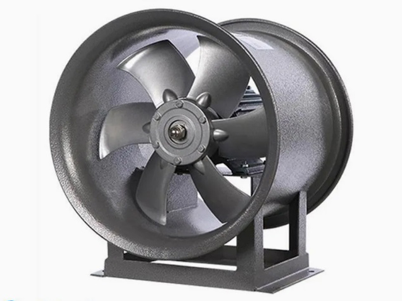
What are the machining processes used for processing axial fan housings
- Process : Sheet metal - Welding
- Material : Carbon steel
Heavy-Walled Flange Milling-Turning Machining and Flaw Detection
- Process : Machining - Turning Milling compound
- Material : Alloy steel
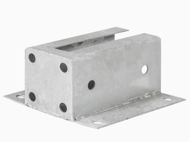
Machining Process Analysis of Carbon Steel Fixed Anchor Plates
- Process : Machining - CNC milling or milling machining
- Material : Carbon steel
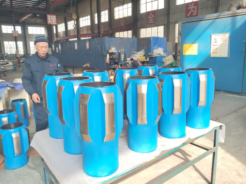
Drill Stabilizers Applied in Oil Drilling Platforms
- Process : Machining - Five-axis machining
- Material : Alloy steel
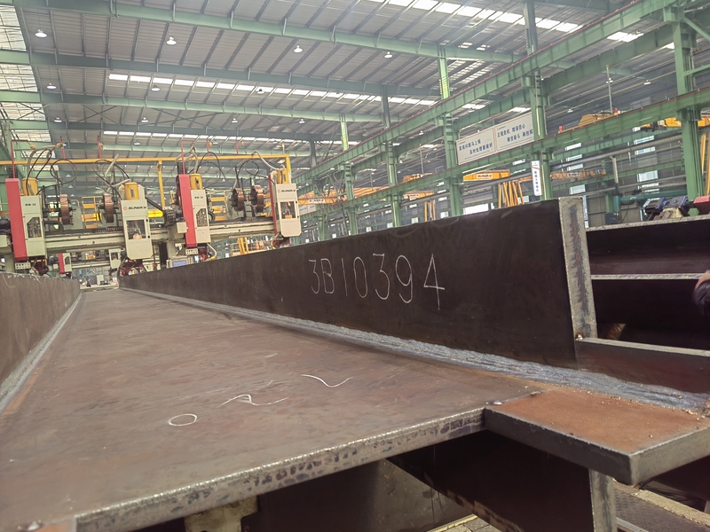
Custom Fabrication of S355JR Welded H-Beams for Construction Projects
- Process : Sheet metal - Welding
- Material : Carbon steel
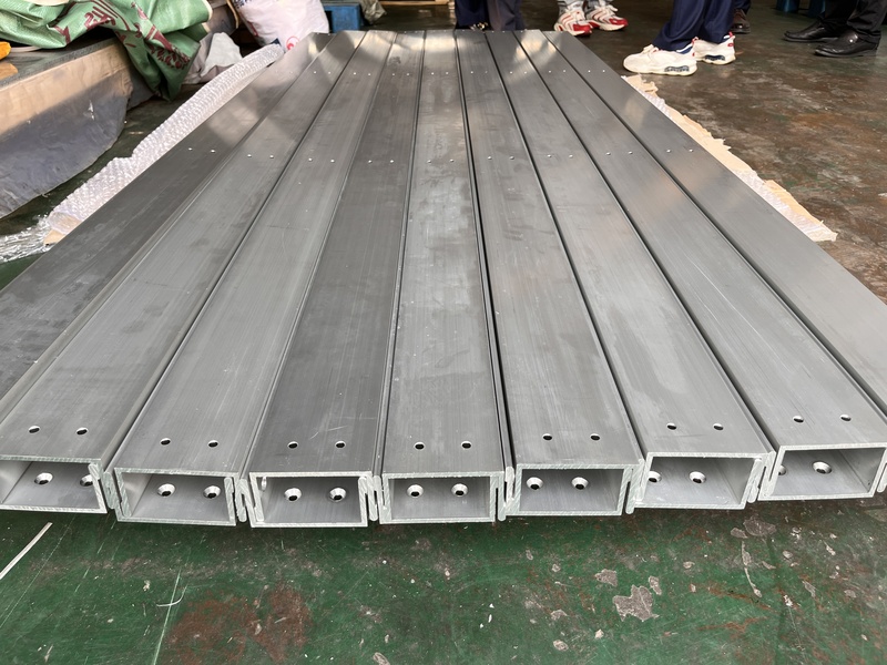
Precision Machining of U-Steel Profiles for Building Applications
- Process : Stamping - General stamping
- Material : Aluminum
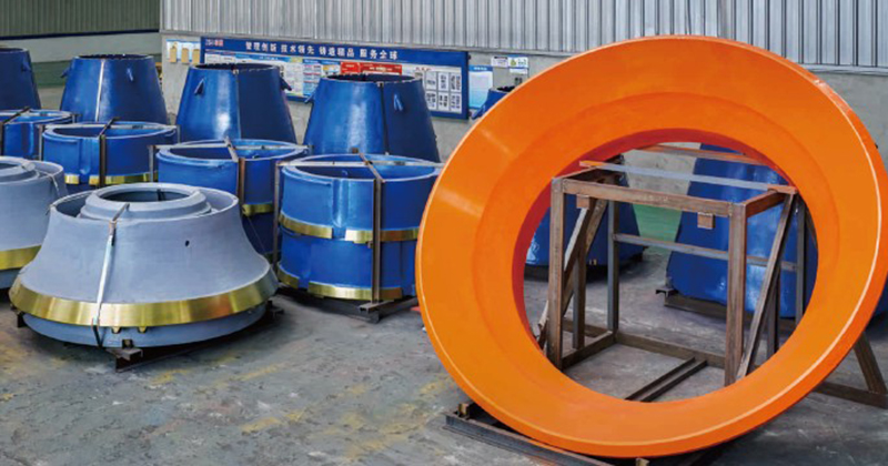
Cone Crusher Mantle
- Process : -
- Material :
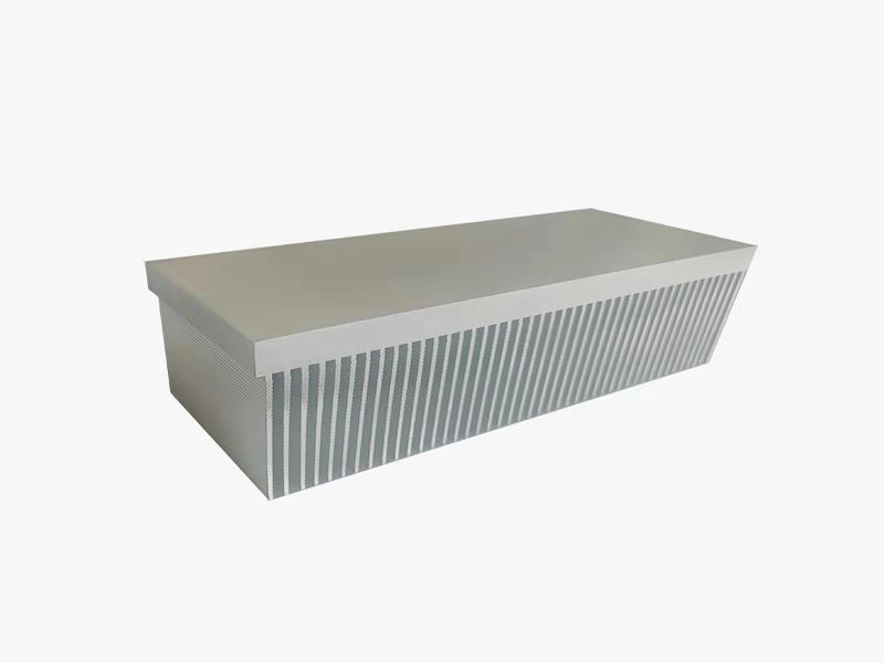
Innovative skiving technology: Breaking through the bottleneck of high-density heat dissipation technology
- Process : Surface treatment - Others
- Material : Alloy steel
More products
MoreWhat are the machining processes used for processing axial fan housings
- Process : Sheet metal - Welding
- Material : Carbon steel
Heavy-Walled Flange Milling-Turning Machining and Flaw Detection
- Process : Machining - Turning Milling compound
- Material : Alloy steel
Machining Process Analysis of Carbon Steel Fixed Anchor Plates
- Process : Machining - CNC milling or milling machining
- Material : Carbon steel
Drill Stabilizers Applied in Oil Drilling Platforms
- Process : Machining - Five-axis machining
- Material : Alloy steel
Custom Fabrication of S355JR Welded H-Beams for Construction Projects
- Process : Sheet metal - Welding
- Material : Carbon steel
Precision Machining of U-Steel Profiles for Building Applications
- Process : Stamping - General stamping
- Material : Aluminum
Cone Crusher Mantle
- Process : -
- Material :
Innovative skiving technology: Breaking through the bottleneck of high-density heat dissipation technology
- Process : Surface treatment - Others
- Material : Alloy steel